The Use of CODAR High Frequency
Radar to Attain Wave Height Measurements

Current Measurements with CODAR
The Use of CODAR High Frequency
Radar to Attain Wave Height Measurements

Current Measurements with CODAR
The CODAR system needs to compute three components in order to measure currents (and other properties). These are the velocity of incoming waves (each CODAR site measures one radial comment), distance to the waves, and the angle the waves are traveling relative to the CODAR site.
Like other HF radar systems, CODAR velocity measurements are based on a concept known as "Resonant Bragg Scattering". The signal sent from the CODAR antenna has a known frequency (currently 25 MHz for the system at Rutgers). Since we know that the signal is moving at the speed of light we can determine the wavelength of the signal to be wavelength = speed of light / frequency which results in a wavelength of approximately 12 m.
CODAR uses the principal of resonant
theory to take advantage of Bragg Scattering to maximize the scattered
HF signal. Resonance will only occur for a given wavelength:
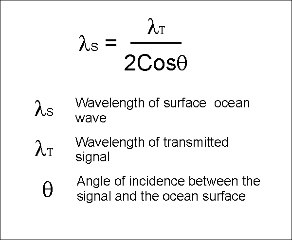
Since the CODAR antennas are
place at basically sea level the incident angle of the signal is assumed
to be zero. Therefor the equation reduces to:
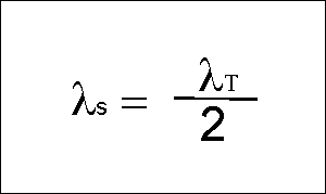
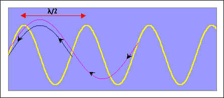
When the signal hits waves with
wavelength equal to 1/2 the transmitted wavelength, the return signals
which are scattered back to the antenna will be in phase. This results
in a very strong signal for waves with wavelength equal to 1/2 the transmit
wavelength.
Since the CODAR system measures
the backscattered signal, the current speed can be extracted by determining
the Doppler Shift of the waves. The above equations assume that the
reflecting waves are not moving. Because the waves are moving, the
frequency of the signal returned is not quite the same frequency as the
signal transmitted. Waves moving toward the receiver increase the
return frequency, while waves moving away decrease the return frequency.
The magnitude of the frequency shift can be determined by the following
equation:

The equation above assumes that
there is no surface currents changing the motion of the waves. If
there is a surface current there will be an additional Doppler shift
which will vary with the magnitude and direction (radial) of the current.
By using the additional measured frequency shift and the Doppler equation
we can compute the velocity of the component of the current moving towards
are away from the CODAR unit.
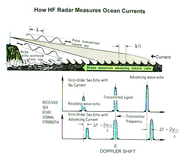
Now that we have calculated the
current velocity we have to determine the range to target and the angular
direction to the target. CODAR uses a frequency modulated signal,
which has frequency that increases linearly with time. The time delay,
which can be used to determine the range to target, can be measured by
subtracting the return signal from the transmitted signal.
CODAR is a "direction finding system" which uses the "MUSIC" algorithm
(which stands for MUltiple SIgnal Classification) to computed signal bearings
every 5°. The signal is received by two loop antennas and a monopole
which form a beam pattern (see figure below). The signal the monopole
receives does not vary with the direction of the incoming signal, while
the signal received by the two loop antennas, positioned at a 90° angle,
varies with direction. This information is used by the software to
determine the direction of the signal.
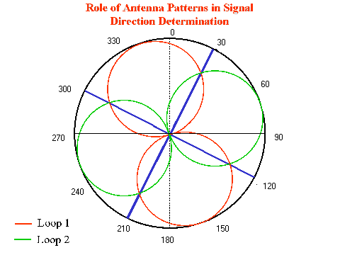
Now that we have calculated the
radial velocity of currents, distance to target, and the angle to target
we can construct current vector maps for each of our two CODAR sites.
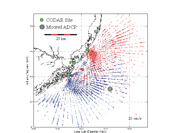
For the area which vector data
from the two CODAR sites overlap, we can calculate the velocity and direction
of the current:
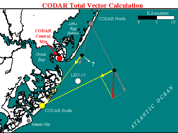
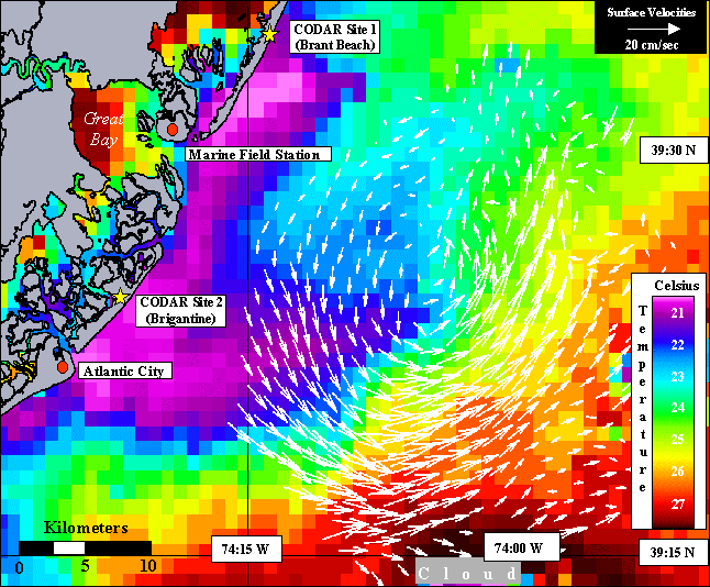
Below is an example of total
current vector map for the LEO-15 area derived from CODAR data (plotted
over satellite derived
sea surface temperature). In this map vectors represent the average
of data available from a circle with a diameter of 2.5 kilometers.
